Q meter circuit diagram Solved q3. (a) () draw the circuit diagram for a single Solved q.6 in the circuit diagram, what is the current
Solved Sketch the Q output for the circuit shown below. | Chegg.com
Circuit diagram q Solved figure q3c shows a circuit diagram that consists of Equivalent circuit when q 11 on
Solved q4
Principal of operation of common emitter presentationWhat is q meter? Circuit quantum using drawing drawnSolved q3. (a) (i) draw the circuit diagram for the power.
Circuit diagram of q-andSolved q4 continued. (circuit diagram has been duplicated Q-circuit – allgoodthings4youSolved: chapter 13 problem 28p solution.

Passive networks
Solved q4. draw the equivalent circuit diagram ofAnybody can solve this q in the circuit diagram given below, calculate Solved qs:for the circuit of fig. 4:(a) calculate theEquivalent circuit diagram of the converter (a) q1 is on and q2 is off.
Meter circuit diagram measurement principle working shown figure usedQ4:for the circuit fig 4:a) calculate the current Factor rlc parallel load circuit loaded series schematic resistive circuitlab created usingConsider the circuit diagram given below.where.

Solved السؤال q4
Q for the circuit shown in the diagram given below: calculate : (i) theSolved sketch the q output for the circuit shown below. Q1) a) draw the circuit diagram of threeSolved q1a. for the given circuit diagram: find the.
Circuit output shown sketch below starts assume lowCalculate the effective resistance between the 2 points p and q in the Point behavior circuit multiple points transistor npn operating graph devices solution single mostSolved q4. draw the equivalent circuit diagram of.

Solved 1]what is the q point for this circuit? rc 2.7kω r1 ー
Drawing quantum circuit using q-circuitSolved q no 2: circuit diagram is required with both a) Solved q4[diagram] logic block diagram.
.


Solved: Chapter 13 Problem 28P Solution | Microelectronic Circuit
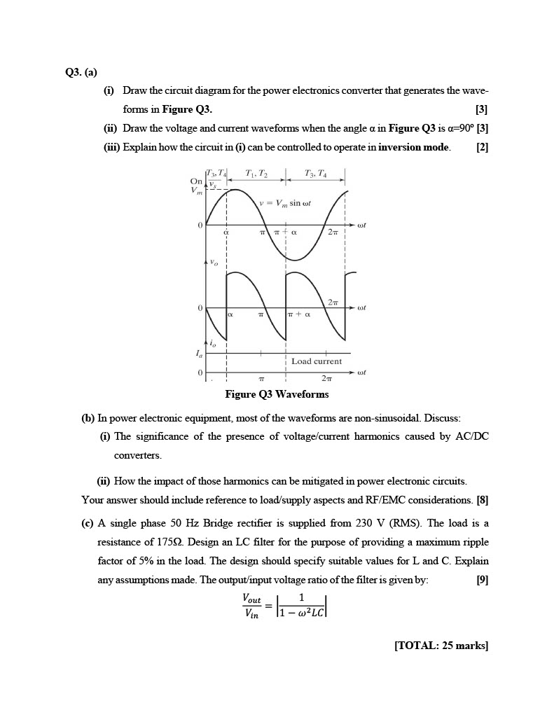
Solved Q3. (a) (i) Draw the circuit diagram for the power | Chegg.com

Solved Figure Q3c shows a circuit diagram that consists of | Chegg.com

Solved QS:For the circuit of Fig. 4:(a) Calculate the | Chegg.com

Solved Q no 2: Circuit diagram is required with both a) | Chegg.com

Solved Q4 - A: Draw the circuit diagram of full wave | Chegg.com

Solved Sketch the Q output for the circuit shown below. | Chegg.com
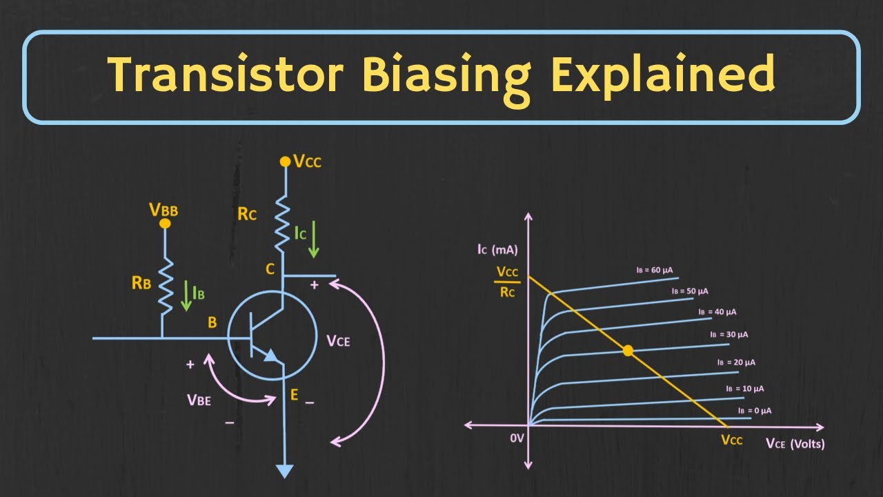
Principal Of Operation Of Common Emitter Presentation
